Pin Conflicts
- When the Deneyap Camera is connected, do not make any external connections to the camera pins.
- While using the built-in 6-axis inertial measurement unit, external connections can be made to the D10 (SDA) and D11 (SCL) pins via an I2C interface with the same pin configuration; however, do not make any other external connections to these pins.
- While using the built-in microphone, do not make any external connections to the D12 and D13 pins.
- During code (firmware) upload, do not make any external connections to the TX (D2) and RX (D3) pins. After the upload process is complete, if you are not using these pins for UART communication, you may make external connections.
- During code (firmware) upload, do not make any external connections to the D8 (BOOT) pin. After the upload process is complete, you may make external connections.
- If an external connection is provided via the I2C connector, external connections can be made to the D10 (SDA) and D11 (SCL) pins via an I2C interface with the same pin configuration; however, do not make any other external connections to these pins.
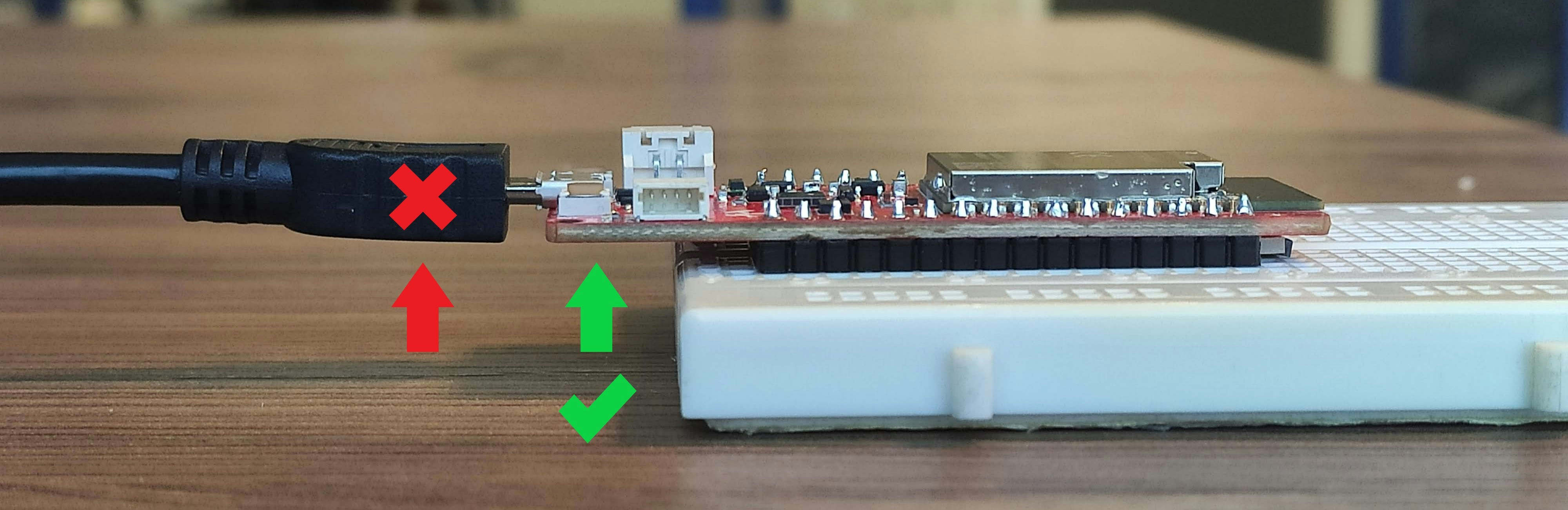
Assembly
When removing your board mounted on a breadboard (prototype board) or a similar unit, be sure to carefully hold it by the edges as shown in the image to avoid damaging the USB port.