- Operating Voltage: 3.3V
- Dimensions: 25.4 mm x 25.4 mm
- Weight: 4 g (pins soldered)
- I2C Address:
- 0x32 default address
- 0x3D address when ADR1 is soldered
- 0x3E address when ADR2 is soldered
- 0x3F address when ADR1 and ADR2 are soldered
- The product includes 1 I2C connection cable, 10 cm in length.
Header (Left)
Header (Right)
I2C Communication Connectors
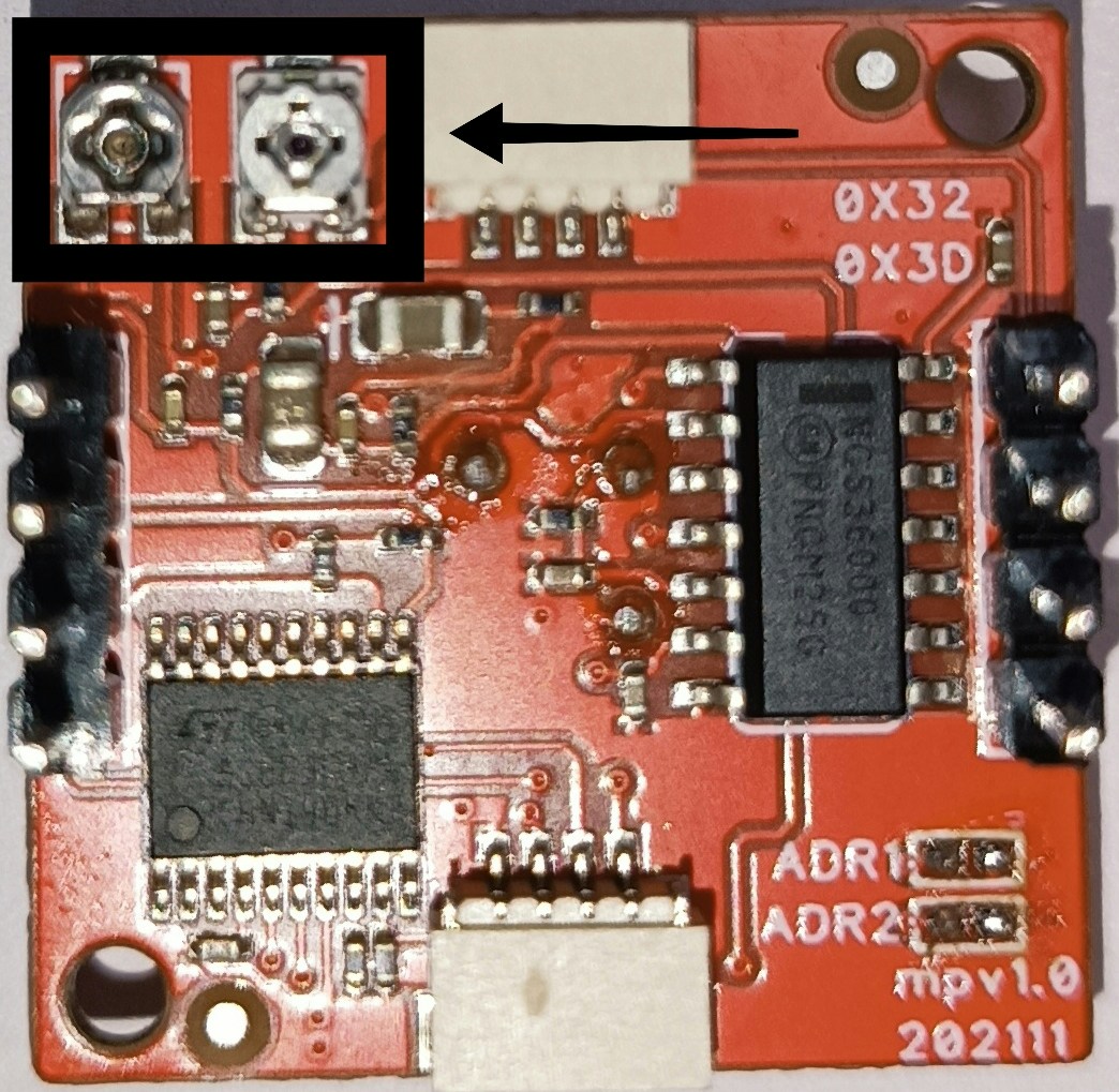
Trimpot
- The trimpots located on the back of the Deneyap Motion Detection Module are shown in the image below. From left to right, the trimpots are used to adjust the detection range and the duration of sending the value 1 (High) when motion is detected.
- When the left trimpot is turned clockwise, the resistance value increases; as the resistance increases, the detection range can be increased up to its maximum value.
- When the right trimpot is turned clockwise, the resistance value increases; as the resistance increases, the duration of sending the value 1 (High) after motion is detected can be extended.