Pin Conflicts
- During code (firmware) uploading, do not connect any external circuitry to the D13 (BT) pin. After the upload process is completed, an external connection may be made.
- During code (firmware) uploading, do not connect any external circuitry to the TX (D1) and RX (D0) pins. After the upload process is completed, if these pins are not used for UART communication, external connections may be made.
- If an external connection is provided via the I2C connector, an external device with the same I2C pin configuration may be connected to the D8 (SDA) and D7 (SCL) pins; however, aside from this case, do not connect any external circuitry to these pins.
Mounting
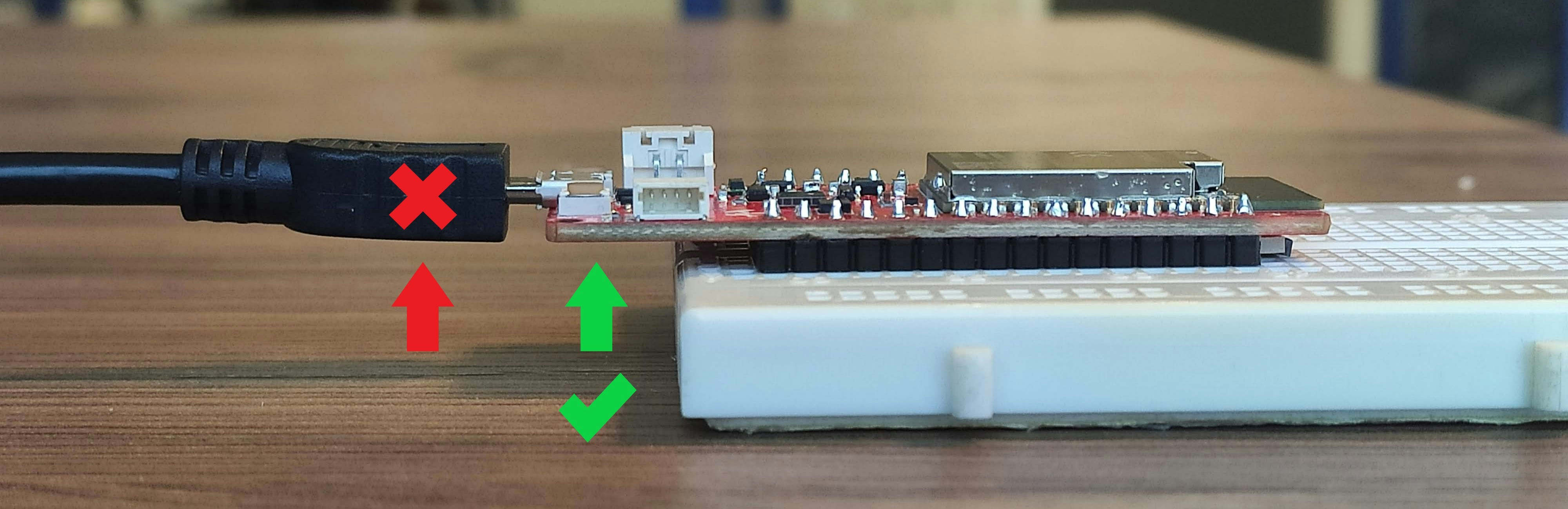
When removing the board from a breadboard or a similar platform, hold it carefully from the edges as shown in the image to prevent damage to the USB port.